
LR/HR
The LR/HR method was developed from the original Shock Pulse Method for condition diagnosis of rolling element bearings. It allows the precision analysis of oil film condition in the interface between the outer and inner races and contains calculation models for finding the optimal lubricant.
Features
-
Fast, easy, and reliable diagnosis of bearing condition
-
Easy-to-understand condition evaluation in green-yellow-red scales
-
Precision analysis of oil film condition in the interface between the outer and inner races, and calculation models for finding the optimal lubricant
-
Use with SPM Spectrum to verify the source of high shock pulse readings
Technical description
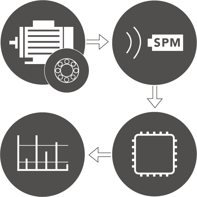
Throughout their lifetime, bearings generate shocks in the interface between the loaded rolling element and the raceway. As these shocks 'ring' the shock pulse transducer, it outputs electric pulses proportional to the shock magnitude. Unlike vibration transducers, the shock pulse transducer responds at its carefully tuned resonance frequency of about 32 kHz, thus allowing a calibrated measurement of the shock pulse amplitudes.
Measuring LR/HR
The transducer type and measuring procedure are the same as for the dBm/dBc method. Shock pulses from the bearing are propagated through the material and picked up by the transducer. The transducer converts the shocks to electric signals, which are processed to provide a carpet value and a peak value.
The shock pulse meter counts the rate of occurrence (incoming shock pulses per second) and varies the gain until two amplitude levels are determined:
- HR = high rate of occurrence, quantifying the shock carpet (approx. 1000 incoming shocks per second).
- LR = low rate of occurrence, quantifying the strong shock pulses (approx. 40 incoming shocks per second).
LR and HR are 'raw values', measured in dBsv (decibel shock value).
Input data
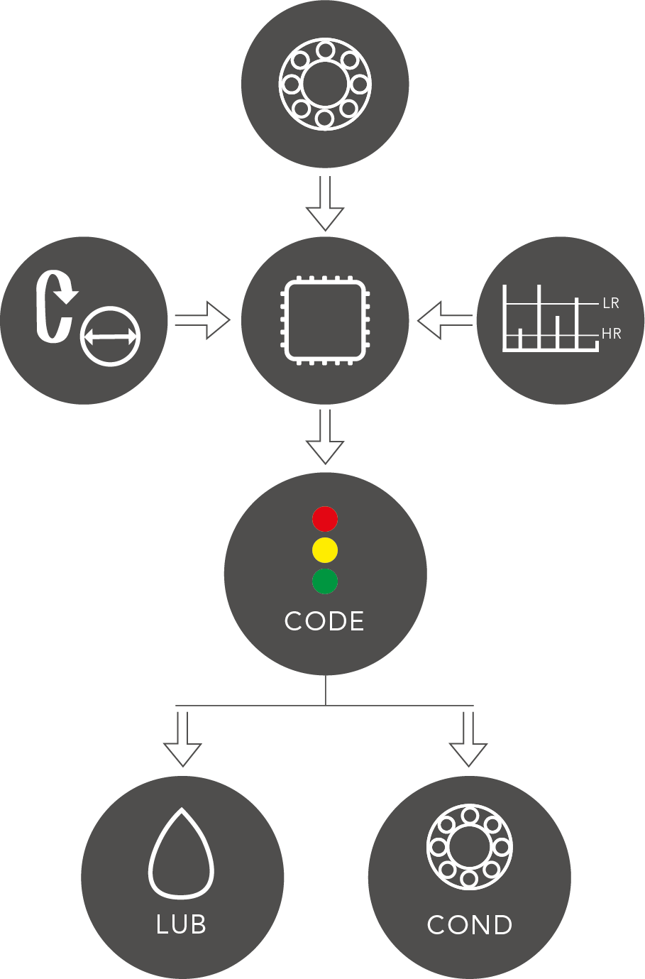
The LR/HR method requires more precise data on the bearing, because bearing geometry, as well as size and speed, affect the shock carpet and thus the analysis of oil film condition in healthy bearings. The rpm is needed, as well as a definition of the bearing type and size, ideally input by stating the ISO bearing number, which links to the bearing catalog in the Condmaster software.
Evaluation
The shock carpet and peak values, along with the bearing geometry, size, and speed provide an evaluation of the bearing lubrication and potential damage.
After the measurement, the following information is provided:
- a general description of bearing condition (CODE);
- a value for oil film condition (LUB);
- a value for surface damage (COND)
A LUB no. of 0 means dry running. This value increases with oil film thickness. A COND no. of around 30 indicates surface stress or early damage. This value increases with damage severity. The general assessment is:
CODE A Good bearing
CODE B Poor lubrication
CODE C Dry bearing, risk of damage
CODE D Damage
LUBMASTER, a part of the Condmaster diagnostic software, uses the shock values and data on lubricant type, viscosity, load, and operating temperature to calculate the bearing's life expectancy under present condition. It also calculates the effect of changes in oil type and viscosity.
Calibration
The accuracy of the LR/HR method is increased by a calibration factor (COMP no.), used in case of bearings with minimal load or poor-quality measuring points (in both cases the signal strength is below normal). On the basis of the bearing's catalog data and lubricant properties, the instrument calculates the normal shock level for a good bearing and compensates for an abnormally low signal before returning the evaluation results.
Analyzing LR/HR
By analyzing the shock pulse measurement in the frequency domain, the source of the shock pulses can be determined. The purpose of 'SPM Spectrum' is to verify the origin of high shock pulse readings. Shocks generated by damaged bearings typically have an occurrence pattern matching the ball pass frequency over the rotating race. Shocks originating from damaged gears, for example, exhibit other types of patterns, while random shocks from disturbance sources have none.
The frequency patterns of bearings are preset in the Condmaster diagnosis and analysis software. Linking the symptom group 'Bearing' to the measuring point allows the user to highlight a bearing pattern by clicking on its name. Other symptoms can be added when appropriate. Finding a clear match of a bearing symptom in the spectrum is proof that the measured signal originates from the bearing.