
dBm/dBc
Part of the original Shock Pulse Method (SPM), dBm/dBc is used to obtain a fast, easy, and reliable diagnosis of the operating condition of rolling element bearings.
Features
-
Fast, easy, and reliable diagnosis of bearing condition
-
Easy-to-understand condition evaluation in green-yellow-red scales
-
Use with SPM Spectrum to verify the source of high shock pulse readings
Technical description
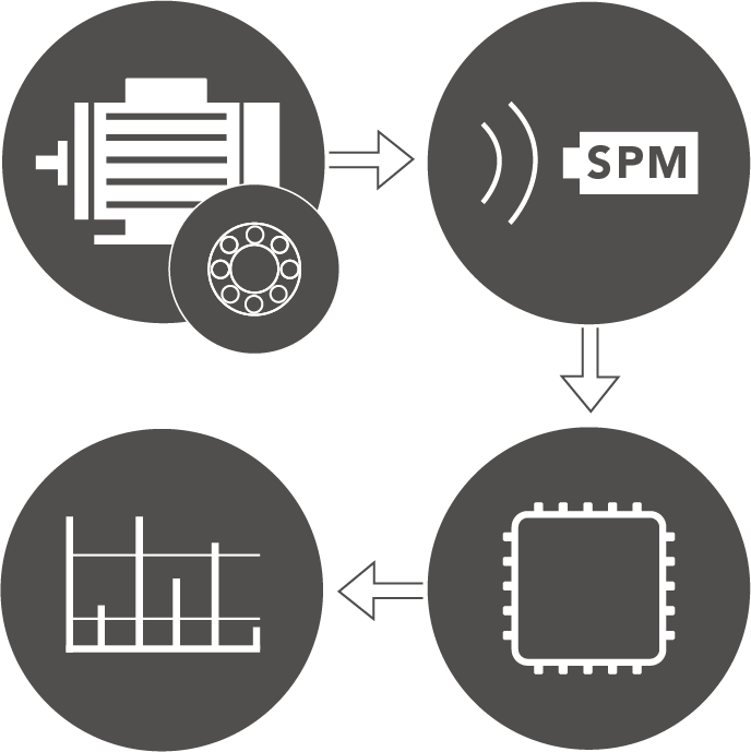
Throughout their lifetime, bearings generate shocks in the interface between the loaded rolling element and the raceway. As these shocks 'ring' the shock pulse transducer, it outputs electric pulses proportional to the shock magnitude. Unlike vibration transducers, the shock pulse transducer responds at its carefully tuned resonance frequency of about 32 kHz, thus allowing a calibrated measurement of the shock pulse amplitudes.
Measuring dBm/dBc
Shock pulses from the bearing are propagated through the material and picked up by the transducer. It converts the shocks to electric signals, which are processed to provide a carpet value and a peak value.
The shock pulse meter counts the rate of occurrence (incoming shock pulses per second) and varies the measuring threshold until two amplitude levels are determined:
- The shock carpet level (approx. 200 incoming shocks per second). This level is displayed as dBc (decibel carpet value).
- The maximum level (greatest incoming shock under 2 seconds). This level is displayed as dBm (decibel maximum value).
Using a flashing indicator or earphones, the operator can establish a peak value by increasing the measuring threshold until no signal is registered. Because of the very large dynamic range, shock pulses are measured on a decibel scale (1000 x increase between 0 and 60 dB).
Shock pulse amplitude depends on three basic factors:
- Rolling velocity (bearing size and rpm)
- Oil film thickness (distance between the metal surfaces in the rolling interface). The oil film thickness depends on lubricant supply as well as alignment and load.
- The mechanical state of the bearing surfaces (roughness, stress, damage, loose metal particles).
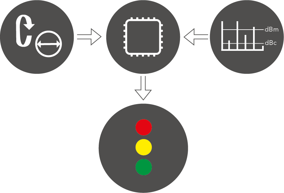
Input data
The effect of rolling velocity on the signal is neutralized by entering rpm and shaft diameter as input data, with 'reasonable accuracy'. This sets an initial value (dBi), the starting point of the 'normalized' condition scale.
Evaluation
The result from the dBm/dBc measurement is the bearing condition data, evaluated in green-yellow-red.
The initial value and the range of the three condition zones (green-yellow-red) have been empirically established by testing bearings under variable operating conditions.
The maximum value places the bearing into the condition zone.
The height of the carpet value and delta (dBm minus dBc) can indicate lubrication quality or problems with bearing installation and alignment.
Analyzing dBm/dBc
By analyzing the shock pulse measurement in the frequency domain, the source of the shock pulses can be determined. The purpose of 'SPM Spectrum' is to verify the origin of high shock pulse readings. Shocks generated by damaged bearings typically have an occurrence pattern matching the ball pass frequency over the rotating race. Shocks originating from damaged gears, for example, exhibit other types of patterns, while random shocks from disturbance sources have none.
The frequency patterns of bearings are preset in our diagnosis and analysis software Condmaster. Linking the symptom group 'Bearing' to the measuring point allows the user to highlight a bearing pattern by clicking on its name. Other symptoms can be added when appropriate. Finding a clear match of a bearing symptom in the spectrum is proof that the measured signal originates from the bearing.